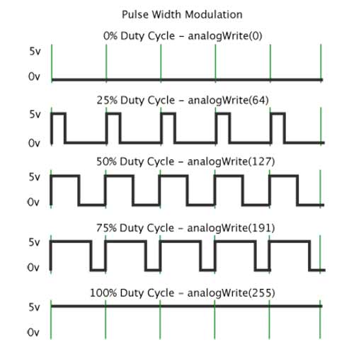
Digital is not driven from 3.5V to 5V, it is driven from 0V to VDDoperating. Look carefully at the output of the uProcessor. The output voltage reads that the output is from. Means the trigger voltage can be in the range of 3.5V to 5 volts. Does not mean switch from 3.5 volts to 5 volts. The signal voltage spec reads 3.5 volts to 5 volts. The Block diagram shows the trigger xistor is connected to ground. The connection to the uProcessor is a digital out. I do not think you require a voltage divider from looking at the spec sheet. I want to know if it is possible to change the PWM output voltage to 1.5V or if I should just use two voltage dividers. Since the voltage of the PWM alternates from 0V to 5V, I want to possibly output 0 to 1.5V out of the PWM then add 3.5V with a voltage divider to the signal to then put it into the sensor.

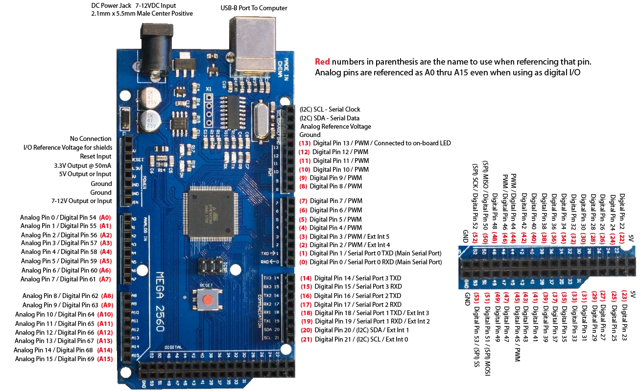
I am using an Arduino mega 2560 and I want to use Analogwrite to output a PWM voltage to an optical sensor but the sensor requires a pulsing signal from 3.5V to 5V.
#Arduino pwm pin 3 serial
Serial.println(volt_val) // prints the value of the sensor to the serial monitorĭelay(10) // wait for this much time before printing next value dist_val = val0.0714285714 // converts voltage output to mm Volt_val = (val/1023.0) 5 // converts signal out put to volts Val = analogRead(sensorpin) // reads the value of the sensorĪnalogWrite(PWMpin, duty_cycle) // generates a modulated signal output from PWMpin PinMode(PWMpin, OUTPUT) // declare PWMpin as an output The pinMode(), digitalRead(), digitalWrite() functions control the operation of non-PWM pins. Arduino UNO board consists of 14 digital Input/Output pins, where pin 11, 10, 9, 6, 5, and 3 are PWM pins. PinMode(sensorpin, INPUT) // declare sensorpin as an input We can control the effective voltage of the DC motor in Arduino by regulating the PWM duty cycle.

Serial.begin(9600) // starts the serial monitor Void setup() // Black wire is ground and Yellow wire is power (5v)

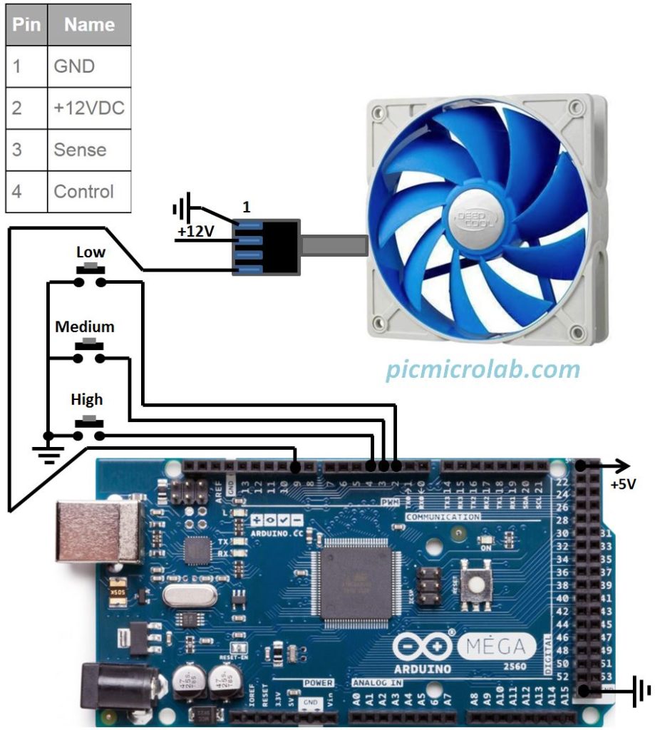
float res = 0.01 // Resolution in mm (10 micrometers) Int val = 0 // variable to store the values from sensor(initially zero) Int PWMpin = 2 // digital PWM pin to output to sensor (Red wire) Int sensorpin = 0 // analog pin used to connect the sensor (Green wire)
#Arduino pwm pin 3 code
The code ends up just printing the same 4.68 volts constantly. That's what I thought, but I couldn't get it to work with the basic Arduino code with PWM output and the duty cycle the sensor spec sheet recommends.


 0 kommentar(er)
